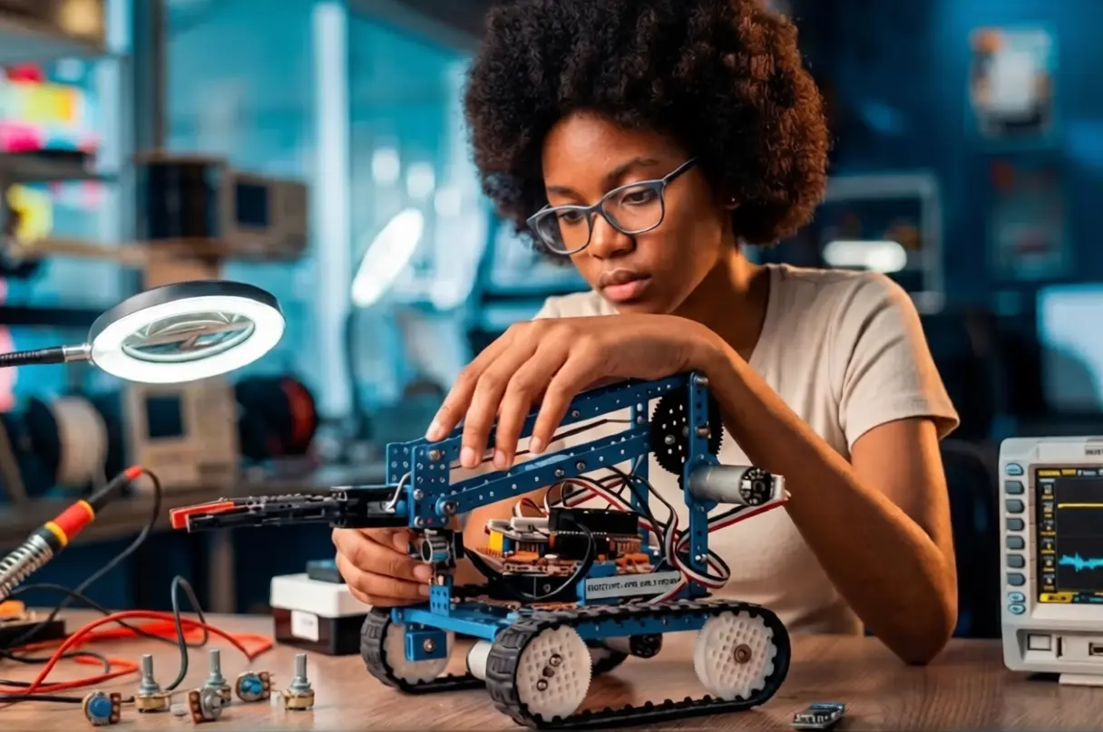
Robotics 101: a free beginner's robotics course
Welcome to this free beginner's robotics course, designed to take you from zero to a working first robot. Robot programming is not about randomly assembling gadgets: it is about connecting logic (code) to the physical world (motors, sensors, current) — the same building blocks used in IoT. This guide takes you step by step from the basics of electronics to a small autonomous robot, with the core skills of a robotics engineer in sight.
Overview: how a robot works
A robot runs continuously in a Sense → Decide → Act loop:
1. Sense: sensors turn a physical phenomenon (a distance, light, a sound) into an electrical signal.
2. Decide: a microcontroller (the "brain") compares these signals against rules you have programmed.
3. Act: the robot moves thanks to actuators (servo motors for a precise angle, DC motors for continuous rotation).
Two ideas to keep in mind from now on:
Sensors are noisy: their measurements are never perfectly accurate. Advanced robots use filters to "clean up" this data instead of trusting it blindly.
All components must share a common ground (the same electrical reference point). Without it, signals become unstable. We come back to this at the end, as it is a classic trap.
Module 1 — The basics
1. Anatomy of a robot
What sets a robot apart from a simple machine is the Sense → Decide → Act loop. A machine performs a fixed task; a robot senses its environment, thinks, then reacts.
To understand the hardware, compare it to the human body:
The human body | On the robot | Role |
|---|---|---|
Eyes / ears | Sensors | Turn the physical world into a signal |
Brain | Microcontroller | Runs the logic, processes the data |
Muscles | Actuators (motors) | Turn electricity into motion |
Blood | Power supply (battery) | Provides the necessary current |
Skeleton | Chassis | Structure and mounting brackets |
Your starting platform: an Arduino Uno or Nano board. It is the most common entry point for beginners. It plays the role of the central nervous system.
2. Electronics basics
Before programming the "thinking", you need to master the medium of "action": electricity.
The water circuit analogy
Imagine a network of pipes:
Voltage (V) = the water pressure. It is what pushes the current.
Current (I) = the flow rate. It is the quantity of electrons flowing.
Resistance (R) = the diameter of the pipe. A narrow pipe slows the flow.
Ohm's law
The basic equation of electronics:
V = I × R
Example: calculating the resistance for an LED
You want to light a small red LED (which handles 18 mA, i.e. 0.018 A) with a 9 V battery. You need a resistor "in series" to limit the current, otherwise the LED burns out.
Careful, a classic trap: an LED is not a simple resistor. It already "uses up" part of the voltage as current passes through, called the forward voltage. For a red LED, it is around 2 V. You must account for it in the calculation, otherwise you greatly overestimate the resistance needed.
The initial version calculated R = 9 V / 0.018 A = 500 Ω . That is wrong.
The problem: an LED is not a simple resistor. It already "uses up" part of the voltage as current passes through, called the forward voltage. For a red LED, it is around 2 V.
The correct formula accounts for this voltage drop:
R = (supply voltage − LED voltage) / current R = (9 V − 2 V) / 0.018 A R = 7 / 0.018 ≈ 390 Ω
In practice you would pick a 390 Ω resistor (standard value) or 470 Ω to be safe. Remember: always subtract the LED voltage before dividing.
Useful detail: the resistor can be placed before or after the LED, it makes no difference. Its only role is to limit the current flowing through the branch.
The breadboard
It is a board that lets you wire a circuit without soldering, so you can easily test and modify it.
Power rails (the long + and − lines on the sides): distribute current across the whole board. Signal lines (the rows of 5 holes): the 5 holes in a row are electrically connected to each other. The central groove: it splits the board into two halves that do not touch. Handy for placing integrated circuits.
3. The microcontroller and programming your first robot
Robot programming starts here: a microcontroller bridges your code and the physical world by translating your logic into voltage variations on its pins. This same principle — a small controller driving sensors and actuators — is also the basis of most connected objects in IoT.
Getting started with the Arduino IDE
1. Choose the board: Tools > Board menu, select "Arduino Uno" or "Nano".
2. Choose the port: Tools > Port menu, select the serial port your board is plugged into.
Structure of a program ("sketch")
Every Arduino program has two mandatory blocks:
void setup() : run only once at startup. Used for configuration (for example: declaring that a pin is an output). void loop() : run in a loop, indefinitely. This is where the Sense → Decide → Act logic lives.
The "Blink" program (making an LED blink)
void setup() {pinMode(LED_BUILTIN, OUTPUT); // sets the LED pin as an output}void loop() {digitalWrite(LED_BUILTIN, HIGH); // sets the pin to 5 V → LED ondelay(1000); // waits 1000 ms (1 second)digitalWrite(LED_BUILTIN, LOW); // sets the pin to 0 V → LED offdelay(1000); // waits 1 second}4. Programming cleanly: variables in robot programming
Writing numbers "hard-coded" directly in the code (like 13 ) is a bad habit. If you change your wiring, you shouldn't have to rewrite your whole program.
Type | Keyword | What it is for |
|---|---|---|
Integer | int | Whole numbers (pin numbers, delays) |
Decimal number | float | Precise decimals (distance calculations) |
Text | String | Labels, status messages |
Hard-coded vs. with variables
Beginner: digitalWrite(13, HIGH); → if you move the LED to pin 8, you have to find and replace every 13 .
Clean: digitalWrite(ledPin, HIGH); → you change a single line at the top of the code.
int ledPin = 13; // pin number, defined only onceint blinkDelay = 500; // delay, adjustable in the same placevoid setup() {pinMode(ledPin, OUTPUT);}Define your parameters right at the top of the program: that way you can tune your whole robot by changing a single value.
Module 2 — Sensors, motors and drivers
5. The HC-SR04 ultrasonic distance sensor
To move around, a robot must measure distances. The HC-SR04 "sees" by sending out a very high-pitched (inaudible) sound and measuring the time it takes to come back, like a sonar.
Principle: a 10-microsecond pulse is sent to the Trigger pin. The sensor emits the sound, then waits for the echo. The calculation:
Distance = (echo duration / 2) × 0.0343
We divide by 2 because the sound makes a round trip (to the object, then back). The number 0.0343 is the speed of sound, in cm per microsecond.
The reading code
long duration;float distance;void loop() {digitalWrite(trigPin, LOW);delayMicroseconds(2); // short pause for a clean pulsedigitalWrite(trigPin, HIGH);delayMicroseconds(10); // we trigger the sounddigitalWrite(trigPin, LOW);duration = pulseIn(echoPin, HIGH); // measures the echo's return timedistance = (duration / 2.0) * 0.0343; // converts to centimetres}
6. Servo motors (precise position)
Once the obstacle is detected, you need to move. Two families of actuators:
DC motor: for speed, spins continuously.
Servo motor: for a precise angle (from 0 to 180°).
Feature | DC motor | Servo motor |
|---|---|---|
Movement | Continuous rotation | Precise angle |
Feedback | None (usually) | Internal (it knows its position) |
Signal | Continuous voltage | PWM signal (pulses) |
PWM (pulse-width modulation) consists of switching the current off and on very quickly to simulate a precise position. The Servo.h library handles these complicated details for you.
#include <Servo.h>Servo myServo;
void setup() {myServo.attach(9); // servo signal on PWM pin 9}void loop() {for (int pos = 0; pos <= 180; pos++) { // sweeps from 0 to 180°myServo.write(pos);delay(15);}}
7. The L298N motor driver (dual H-bridge)
An Arduino pin supplies about 20 mA in normal use (40 mA being the absolute limit, never to be aimed for). A DC motor demands far more: connecting it directly to the Arduino destroys the board.
So we use an L298N motor driver as a sturdy intermediary. It takes the high current from the battery and delivers it to the motor, obeying the small signals from the Arduino.
H-bridge: by reversing the direction of the voltage across the motor terminals, you reverse its direction of rotation.
L298N pins:
ENA / ENB: PWM pins that control the speed.
IN1 to IN4: pins that control the direction.
IN1 | IN2 | Motor behaviour |
|---|---|---|
HIGH | LOW | Forward rotation |
LOW | HIGH | Backward rotation |
LOW | LOW | Stop (freewheeling) |
Module 3 — Hands-on projects
8. Project 1: the line-following robot
This robot uses infrared (IR) sensors to stay on a black line. The principle: black absorbs IR light, white reflects it. The robot therefore knows whether it is on the line or beside it.
Differential steering: by spinning the left and right wheels at different speeds, you turn without a steering wheel.
Left sensor | Right sensor | Action |
|---|---|---|
White | White | Straight ahead |
Black | White | Turn left |
White | Black | Turn right |
9. Project 2 (final): obstacle-avoiding robot
This robot combines everything: the HC-SR04 (the "eyes"), a servo (the "neck") and the L298N (the "legs").
The logic:
1. Scan: the servo rotates the sensor to look for a clear path.
2. Slow down smoothly: with the map() function, the closer the obstacle, the more the motor gradually slows down. 3. Choose a path: if the robot is stuck, it stops, compares the distance on the left and on the right, then heads toward the clearer side.
#include <Servo.h>
// Pin definitionsconst int trigPin = 9, echoPin = 10, motorSpeed = 5;const int IN1 = 4, IN2 = 3;
Servo neckServo;void setup() {neckServo.attach(11);pinMode(trigPin, OUTPUT);pinMode(echoPin, INPUT);}void loop() {long duration;float distance;// Distance measurementdigitalWrite(trigPin, LOW); delayMicroseconds(2);digitalWrite(trigPin, HIGH); delayMicroseconds(10);digitalWrite(trigPin, LOW);duration = pulseIn(echoPin, HIGH);distance = (duration / 2.0) * 0.0343;// Gradual slowdownint currentSpeed = map(distance, 15, 40, 0, 255);currentSpeed = constrain(currentSpeed, 0, 255);if (distance > 20) {analogWrite(motorSpeed, currentSpeed); // proportional speedmoveForward();} else {performEvasiveScan(); // stops and looks for another path
}}Module 4 — Safety, troubleshooting and artificial intelligence
10. Power and safety: the golden rules
Never power the motors from the Arduino's 5 V pin. Always use a dedicated battery for the motors (for example a 7.4 V battery).
Connecting batteries in series increases the voltage (more "force").
Connecting them in parallel increases the capacity (more battery life).
The common ground (an absolute must to understand)
A voltage is never an absolute value: it is always a difference between two points. When the Arduino sets a pin to "5 V", it means 5 V relative to its own ground (GND).
If you have two separate power supplies (one for the Arduino, one for the motors) and their grounds are not connected, the two "zeros" do not match. Result: the Arduino sends a "5 V" that the driver cannot interpret correctly, and the robot becomes unpredictable.
The rule: always connect together all the negative terminals ( − / GND) of your power supplies, so that they share the same zero reference.
Checklist before powering on
[ ] Polarity: are the + and − wires in the right place? (reversing them can destroy the hardware)
[ ] Common ground: is the battery's ground connected to the Arduino's?
[ ] Wiring: no loose or poorly inserted wires?
[ ] Syntax: correct capitalisation ( pinMode ) and semicolons present?
11. An overview of artificial intelligence in robotics
Artificial intelligence applied to modern robotics moves robots from fixed rules ( if... then... ) toward state estimation. Because sensors are noisy, we cannot trust them blindly: we use filters to turn uncertain measurements into reliable estimates.
Filter type | Main idea | When to use it |
|---|---|---|
Histogram filter | Splits space into cells and tracks probabilities | Locating yourself in a known map |
Kalman filter | Tracks position with probability curves | Tracking position and speed (low noise) |
Particle filter | Throws out lots of "guesses" and weights them | Complex environments, a "lost" robot |
On the vision side, tools like Google's Teachable Machine let a robot recognise objects with a small neural network, rather than with simple distance measurements.
Module 5 — Your final project
12. The autonomous obstacle-avoiding robot
This guide has taken you through all of a robot's subsystems: electronics, microcontroller logic, sensors, actuators. The final project brings everything together in one working machine.
You will draw on:
Electronics: wiring a circuit with the right resistor (Module 1.2)
Programming: clean setup() and loop(), with variables (Module 1.3–4)
Sensors: reading a distance with the HC-SR04 (Module 2.5)
Actuators: a servo to scan, DC motors via the L298N (Module 2.6–7)
Integration: combining all of this in the Sense → Decide → Act loop (Module 3.9)
Safety: applying the golden rules and the checklist (Module 4.10)
Minimum goal (mandatory): your robot moves forward, detects an obstacle under a given distance, stops, looks left and right, then turns toward the clearer side.
⚠ Advanced extension (optional): the Module 3 code also includes gradual slowdown (via map() ), where speed drops as an obstacle gets closer. It is a first step toward control theory, a subject this guide deliberately only skims (PID, advanced filtering and autonomous navigation go beyond the scope of a beginner course). Wait until your basic robot works well before tackling it.
You are ready to call yourself an "apprentice robotics engineer" when you know how to:
Understand how a robot works at a basic level
Handle simple electronics
Program a microcontroller
Connect and use sensors
Drive motors
Assemble a simple robot
Troubleshoot basic hardware or software problems
This project marks the limit of beginner robotics, not of robotics itself. The natural next steps toward a career as a robotics engineer: industrial robotics, advanced control theory, artificial intelligence and computer vision, connected objects (IoT), ROS2 and autonomous navigation.
This course only covers the basics. To go further and become a robotics engineer, join one of Epitech's programs: